

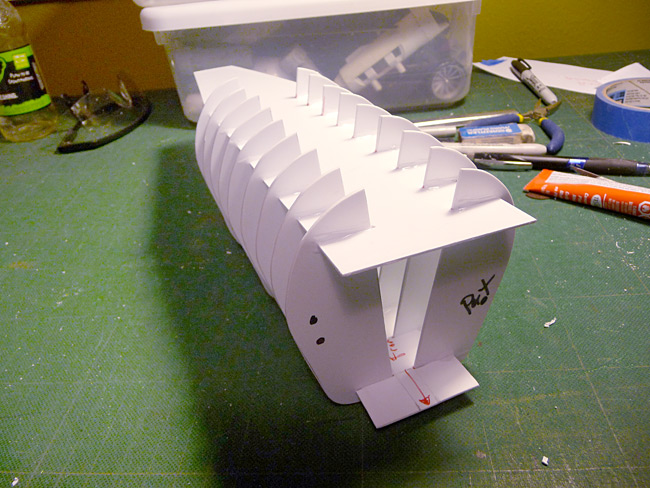
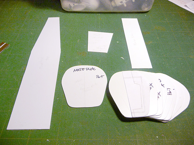
Spent some time today on the bommer. Got the interior ribbing done. Took a long time and was tedious work to make sure everything went together right the first time. Here are the templates/parts initially cut put.
The ribs were made from the same templatw and I wasn't too worried about them being absolutely, perfectly, exactly the same...
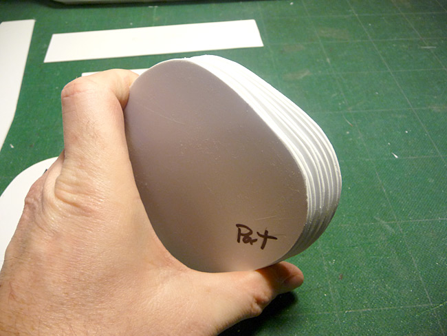
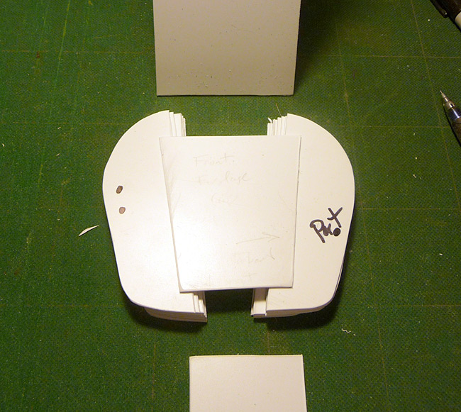
I then sliced a wedge shape out of the middle. I'm not detailing the interior so I wasn't interested in leaving a large inside space and I angled it to be wider at the top to make room for recessing the pilot and adding the top turret gunner. The piece on top of the left and right rib stacks will be glued on the front edge of the floor/top structure to add some rigidity. It will also be where the nose gets glued onto the fuselage of the plane. I'm leaving it off until I can add the superstructure for the wings and tripod mount - easier access.
More to come!
BoLS Lounge : Wargames, Warhammer & Miniatures Forum
Results 301 to 310 of 503
Thread: Sukigod's Ork Waaagh! Log
-
03-05-2011, 11:28 PM #301Chaplain

- Join Date
- Aug 2009
- Location
- Central MN, USA
- Posts
- 370
 http://www.bigshoota.com
http://www.waaaghfest.com/
-
03-05-2011, 11:29 PM #302Chaplain
- Join Date
- Aug 2009
- Location
- Central MN, USA
- Posts
- 370
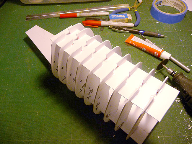
I then used a Dremel to cut slots in the top and bottom supports The depth of the cut determined the angle so cutting them all the same made it easy to align all the rib sections when I was ready. Here's the glued together interior frame from the front...
The rear...
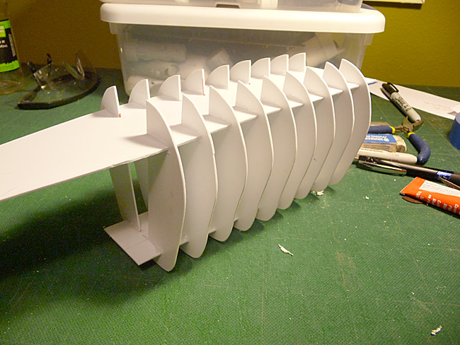
The underside.
And a Barry shot.
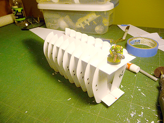
I need to change out the crappy CFL bulb that came with my new angle lamp - color correcting these pics absolutely suck! Taking the Barry shot made me realize how big this thing really is - it's gonna be pretty huge! Oh well.
Later!http://www.bigshoota.com
http://www.waaaghfest.com/
-
03-10-2011, 09:43 AM #303Chaplain
- Join Date
- Aug 2009
- Location
- Central MN, USA
- Posts
- 370
Stopped off at the hardware store at lunch today and picked up some pvc and epoxy putty. I picked up 1x4-way connector, 1xT connector, a male/female threaded connector, a 2' piece of pvc pipe (all in 1.2" dia.) and two tubes of plumbers epoxy putty for around $12. Nice and cheap!
I get home and lay the pieces out for test fitting…
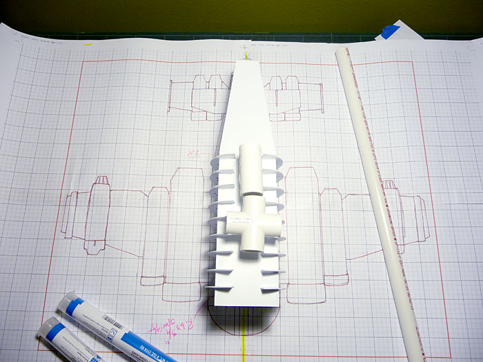
GASP! I had always intended to us 1/2 pvc as my main internal structure so I based my ribbing spacing at 3/4". Way more than enough room, right? Uhhh… As you can see, the connectors are wider than 3/4". Me being the non-genius that I am, didn't take into account that the connectors (which have to fit inside the ribbing too) would be much wider than the 1/2 pipes them selves since they fit OVER/OUTSIDE the actual 1/2' tubing. If I ever do a second blasta boomer, I know to base my spacers on the dimensions of the CONNECTORS! not the pvc pipe I'm using.
This will mean i have to cut out one spacer to let me get the connectors inside - the angles I cut them at hinders this a swell so the Dremel gets a good workout and cutting away some of the interior ribbing to get everything in there - more of this can be seen in the last photo of the post.
Here's rough placement (outside the ribbing) to see where I plan on placing the connector points.
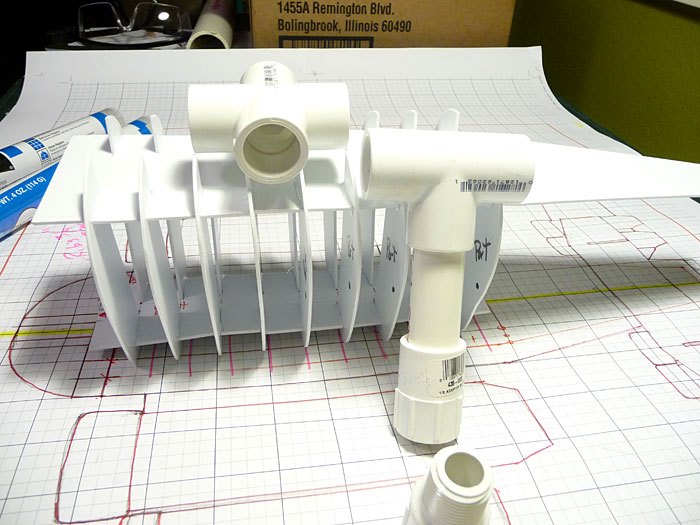
Now, the placement of both the 4-way and the T connector are completely guesswork. I have no idea of how heavy this thing will be in the end, where the actual center of balance will be so I I'm doing a "best guess/cross my fingers" placement. I know pox's build had the center of the wing/fuselage cross point as the center of balance where the tripod connected to the plane. I've decided to change that a little - we'll see if it bites my in the *** later. Because of the estimate weight of the tail I don't think this would work in my case.
If things turn out to be way off balance I'm assuming it'll be in favor of the nose. The way I'm building this (nose to tail), I'll be able to easily hide extra weight in the tail section as I fill it in to counter that. Again, I'm hoping that's how it'll work.
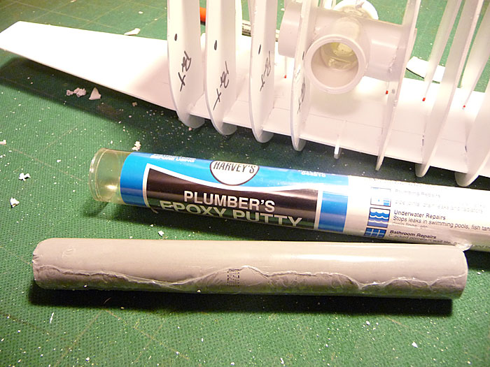
Here's the putty I purchased. I couldn't find the brand pox suggested but I'm pretty sure this is reasonably close - and it's really cheap. It's around $5-$6 a tube. You can see some of the carnage I had to inflict on the internals to get the connectors in there..
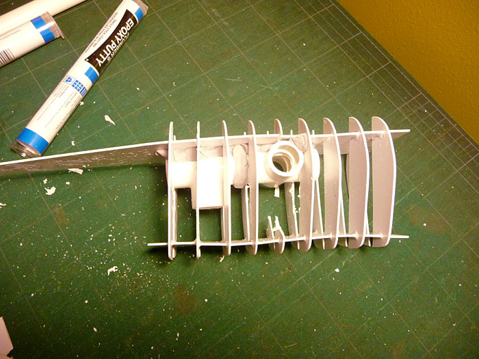
Here's the "backbone" showing the final placement. There will be a short piece coming out of the front side that will be glued to the nose plate and a longer piece extending through the tail to give maximum support across the entire length of the plane. I've decided to leave the side wing connectors open and have a short piece of pvc coming out of the wing to make them removable. PVC fits together pretty snuggly so I'm not to worried about connection strength - the wings won't be that heavy.
I'm hoping to have the rest of the "backbone" finished and puttied down by the end of tonight and maybe started on the main central structure of the wings sometime this weekend.
A note on the putty… I read the instructions inside the tube and they mentioned something about wearing rubber gloves of some sort. I kinda blew this off as being "over protective in this litigious society". Nope, for two reasons. One, not only does it get sticky when you're kneading it, the stuff will get embedded into the pores of your skin and be hell to get off. Remember, this stuff sets up like concrete steel - imagine that in your pores. Second, it gets hot! I was surprised by how much heat is generated by the chemical process while mixing. This does make it a little trick when trying to apply this in tight spaces (as I did) but the latex/rubber gloves were worth it in the long run.
(yes, I spent 15 minutes trying to remove the compound from my skin after the first application).
Later!http://www.bigshoota.com
http://www.waaaghfest.com/
-
03-11-2011, 12:07 PM #304Initiate
- Join Date
- Mar 2011
- Posts
- 2
Monumental (Emphasis on the mental) Undertaking.
This looks like your biggest project yet.
I'm already overwhelmed and I'm just watching you do it.
I cannot wait to see the essential frame complete.
That in it's self will be a great success.
Mad respect for tackling it Suki.
You are indeed da masta.
All I have to say is, I'm glad you are Ork.
-
03-13-2011, 09:47 AM #305Chaplain
- Join Date
- Aug 2009
- Location
- Central MN, USA
- Posts
- 370
Thanks MATPHAT.
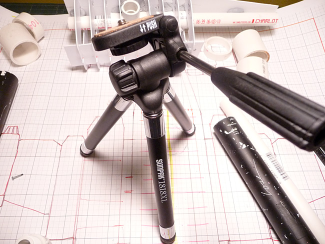
My tripod came in yesterday and got the chance to get it ready late last night. Here now, in excruciating. boring detail, is how I modified the tripod for my bommer.
Here's the original tripod, maybe $20 tops online (Amazon.com I think). It's rated to hold up to 2 pounds but after getting it in the mail and wrenching around with it for a bit I think that is determined by the swiveling head and not the actual tripod support legs themselves.
The stand itself is pretty sturdy. When I was finished I "stress" tested the hold by putting the plane as it is so far on it for normal use, then stacked my two skullhammers on top (as best I could) with different weight distributions and not only did the connection hold fine, the balance stayed pretty stable as well. I'm not worried about this thing falling over one bit.
I disassembled the multi-axis head down to it's component parts. I wanted to see if I could keep the swiveling aspect of the pan head since this will give me more placement options on the table with the skinny legs, then simply turn the plane in the direction I need. The part I'm most interested in is the center pivot/swivel joint. I need this (the black part) to fit inside the threaded pvc connector.
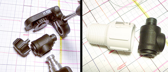
Ten minutes with the bench grinder and viola! The head part fits snugly inside the pvc connector. I drilled a matching hole in the pvc connector so I could pass the lock down screw through it. Because of the way the lock screw was designed, I had to cut the edges of that down so the threads could meet the original swivel head part inside the pvc connector.
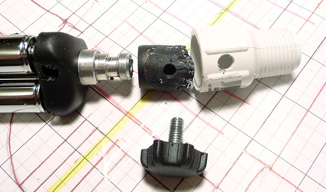
I applied a pit of plumbers putty inside the pvc connector and made sure I spread a thin coating around the inside barrel portion of the connector, then shoved the pan head part into it, centered it on the lock screw hole and added some more putty around the bottom for good measure. After curing I put the whole thing together for testing.
As I mentioned earlier, My biggest concern was "is this gonna hold? Did I cheap out too much and not get a sturdy enough tripod?" My fears were quickly put to rest. Because I changed the way the tripod connection system worked, the listed weight limit for the pod was pretty much nullified. I put some pretty good pressure on that thing, to point where I was going to break something, and it held just fine.http://www.bigshoota.com
http://www.waaaghfest.com/
-
03-13-2011, 09:48 AM #306Chaplain
- Join Date
- Aug 2009
- Location
- Central MN, USA
- Posts
- 370
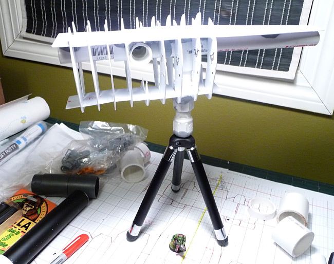
Here's scale shot of the finished support system with a little Barry boy for fun.
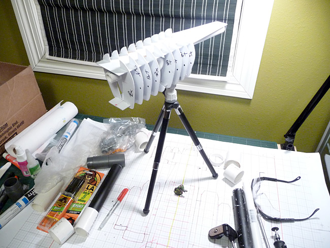
I've started cutting parts for the main engines (as seen in the last pic) and will be starting work on them today. I might switch to the nose for some variety - besides, I'm excited to see all the weapons I can cram into the Deff Arsenal!
Later!http://www.bigshoota.com
http://www.waaaghfest.com/
-
03-13-2011, 02:32 PM #307Brother-Captain
- Join Date
- Jul 2009
- Location
- Minneapolis, MN
- Posts
- 1,348
Brilliant idea to use a tripod. I'll probably end up borrowing that idea for my own flyers.
I'm looking forward to seeing this build progress - always interesting to see your scratchbuilds sukigod.
-
03-17-2011, 09:29 AM #308Chaplain
- Join Date
- Aug 2009
- Location
- Central MN, USA
- Posts
- 370
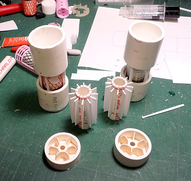
Spent 2 hours last night making the primary engine intakes. Fiddly work but it' s got to be done! Here's how I did it.
There's a couple of different ways to do turbine blades. Some of them include math and geometry. Mine include neither! I completely guessed (as any good mek does) on the number of blades and how to make them even. I choose 12 fan blades.
I started by cutting out 5 similar sized disks. Two for behind the fan blades to glue to and three for cutting the fan blades from. I didn't do any magic measuring of fancy stuff to come up with cutting 8 pie shapes from each. I just wanted to make sure they overlapped a bit and I figured if I squished four more slices into a circle originally dissected by 8, there should be some overlap. If you understood that well enough, here's your degree!
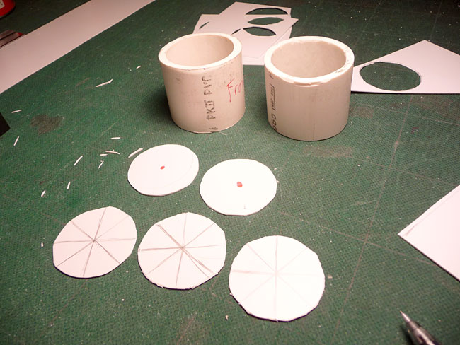
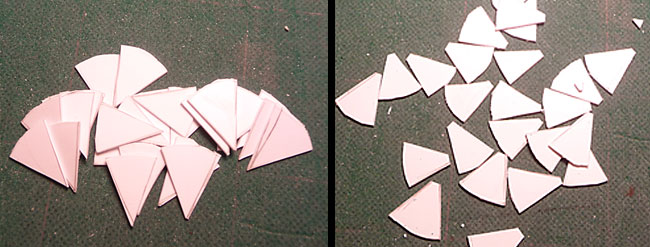
I cut the three disks into pie shapes and then cut the tips of each off. Things get really tight at the center of the turbine if you don't do this. Trying to stack 12 layers of plastic in the middle of the circle will only cause problems so away they go. We'll be covering this part with bullety shaped part anyway.
I made a time-wasting mistake with my first turbine blade by laying the first blade down, the the next - and on and on - until I reached the first one and tried to slide the last blade under the first one. Didn't work. It was nearly impossible to align the blades evenly this way and the glue had a tendency to set more than I would have liked by the time I got all the way around, causing sticky problems. Then i hit on this idea…
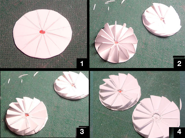
1. Draw out the radians so I know where to line up the fan blades.
2. Glue all the fan blades in place with them all standing up. This was much quicker as I didn't need to worry about jostling the other blades and it was easier to see the markings. (the original wreck of a turbine is upper right)
3. I used the back end of my exacto knife to push the blades down on one another a little at a time. Since the glue was still soft-ish, but still sticky enough to keep t from sliding, the fans kinda hinged down against each other. This kept the blades in place and they automatically went down to the farthest angle possible n their own without any measuring.
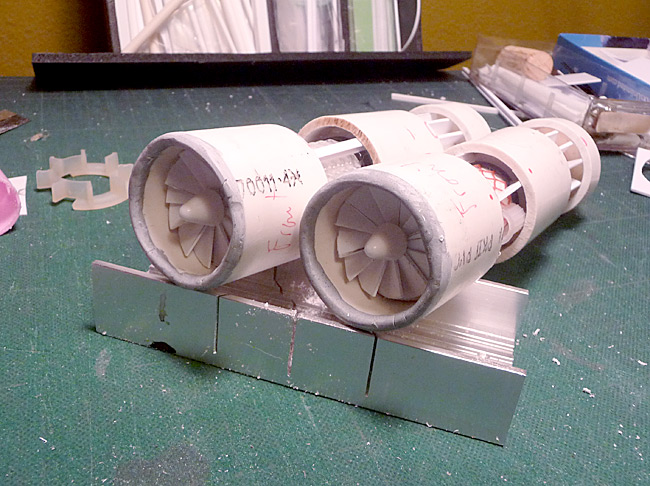
4. Leaving me with this. These are both, finished turbines. Not perfect (I've seen much better) but will work for me.
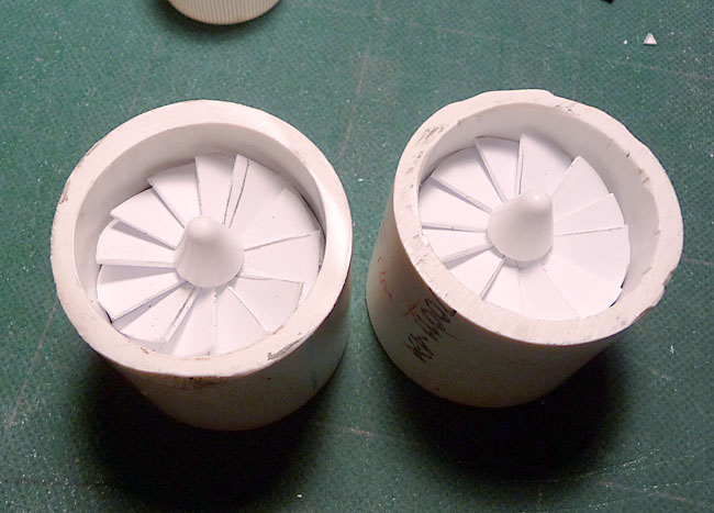
Here's the turbines now glued in place. I just hotglued them in place, they didn't need anything more complicated. I'll be making a rounded edge using putty just like pox did in his build. No need to remake the wheel. Depending on how well this masks the gap between the fan blades and the housing wall, I might try to find a gubbin that will ring the housing to cover it a little - we'll see what the bitz box has.
Later!http://www.bigshoota.com
http://www.waaaghfest.com/
-
03-20-2011, 04:31 PM #309Chaplain
- Join Date
- Aug 2009
- Location
- Central MN, USA
- Posts
- 370
Nice idea marcineczek0! I might try this on the outside engines to see how it looks, might be better when doing smaller turbines too. Thanks!
Ya gotta work on what inspires you when it inspires you, right? Well I was inspired in the middle of the night. I've been playing with some new units and Skorcha Trakks are one of them. I really like how they've been working for me so I set my brain into Hey, work on this in the background" mode about how to build some.
Two things came together at once. I've been using deff koptas without blades and stands to proxy them in the last few games. I then remembered one of our gaming pals bought a bunch of Hot Wheels Batman Tumbler kit things and converted them to Tauros' for his 'umie force. I was the final recipient of the left over track parts. They've been sitting in my bitz boxes for almost a year with nothing to do - until now. My only concern was how well it would fit with the deff kopta bodies.
Here's the two main parts.
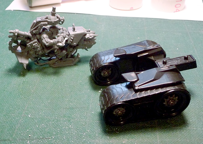
Here's the one on the other for size comparison. Admittedly the tracks are a little wider than I'd like but I think I can make them work.
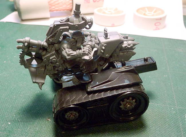
An hour later (and an online shopping trip to purchase two more...) the deff koptas fit snuggly in the middle of them tracks part.
Barry shot with trukk for scale. I'll be adding a platform around the back for a gunner to stand on with the skorcha pintle mounted where the blades were. A bit of armor and spikes to fill out the front and some armor plating to orkify the rest. Thanks to Jason for the tumbler parts!
Later!http://www.bigshoota.com
http://www.waaaghfest.com/
-
03-20-2011, 09:28 PM #310Chaplain
- Join Date
- Aug 2009
- Location
- Central MN, USA
- Posts
- 370
More bommer work done after the initial spaz about the warbuggies...
Here's some parts in subassembly stage.
I've gotten the putty rounding the engine cowlings done, although not the best. I should have done a one extra engine that I tested everything out on first. Could have been helpful with the bad shaping job on the first engine (you'll know it when you look at it. I'm hoping the paint will mask some of that.
Engines!
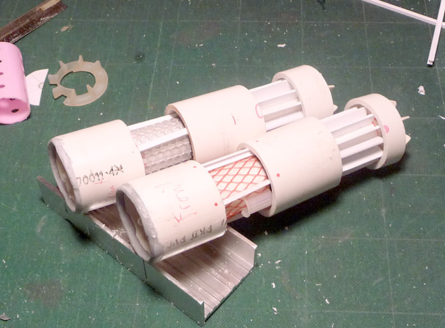
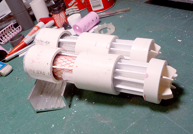
I'm going to figure out the wing attachment method next, then i can move on to the second engines that will be strapped to these. I'll be building the general internal structure and everything that needs to be really strong first. Then I'll go back and add all the detailing and pretty things up so most of the work at the beginning won't be too exciting or beautiful to look at.
p.s. the internal fins at the back are from paint roller end caps. You'll recognize these if you ever painted the inside of houses with rollers
Later!http://www.bigshoota.com
http://www.waaaghfest.com/

 Reply With Quote
